The RPM limit assembly is:
A motor speed feedback + position tracking mechanism
used by the DorRoller 45 controller to determine:
- When the door is fully open
- When the door is fully closed
- How fast the motor is rotating (RPM feedback)
- Whether the door is moving correctly
It works together with the controller’s electronic limit system.
From DorRoller 45 specs:
- The system has “accurate limits” and electronic control features
- Limits are set electronically and stored in the controller logic
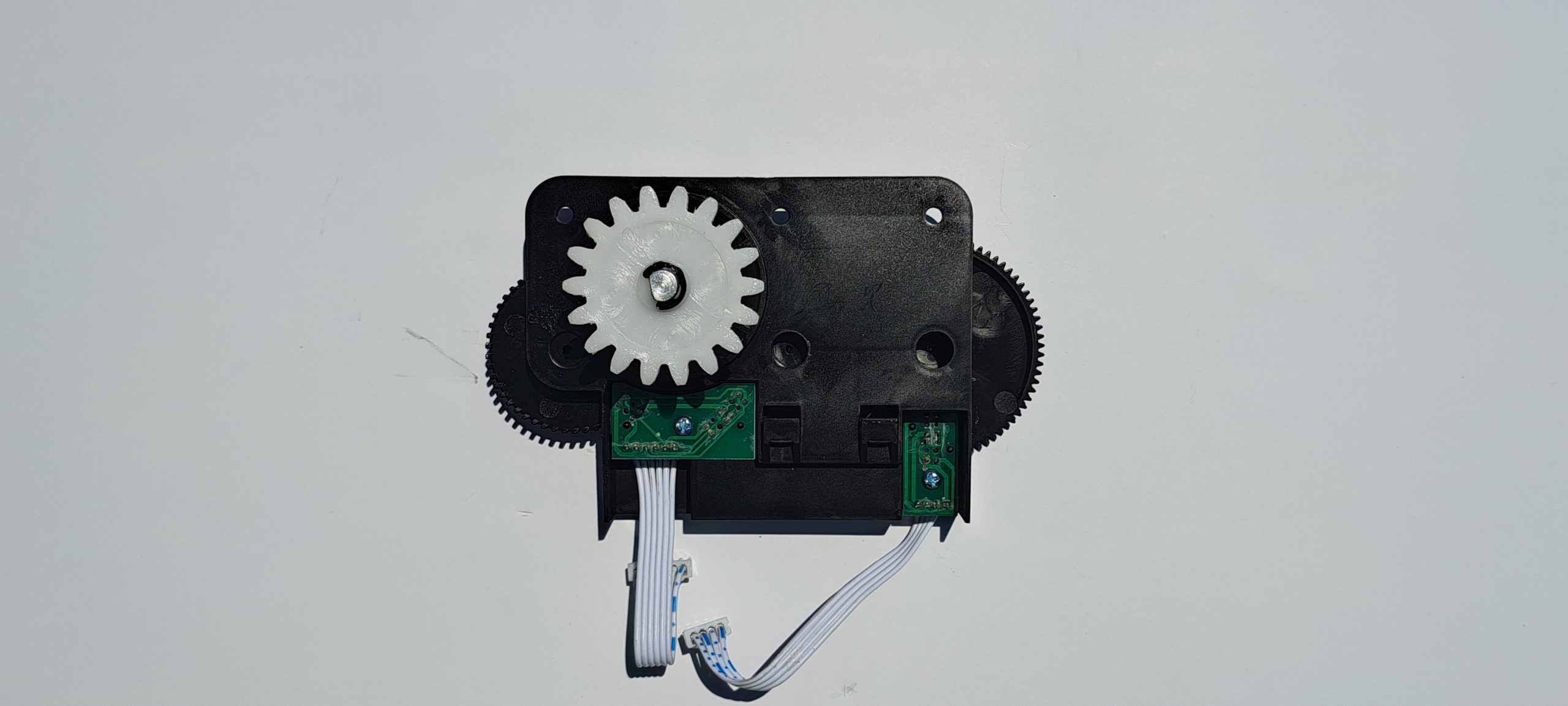
What it actually consists of
The “RPM limit assembly” is usually made up of:
Motor rotation sensor (RPM pickup)
- Typically a Hall-effect or magnetic sensor
- Reads motor shaft rotation
- Generates pulse signals (RPM feedback)
Reference mechanism
- Gear, magnet ring, or encoder disc
- Fixed to motor shaft or gearbox
- Creates repeating signal pattern
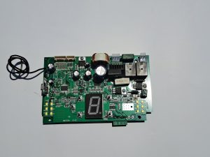
Limit reference system (electronic memory side)
- Controller stores:
- Open position count
- Close position count
- Uses RPM pulses to “count travel distance”
How it works in the DorRoller 45 system
So instead of physical limit switches, it uses:
electronic counting of motor revolutions
Why RPM is used for limits
Unlike older systems with end switches, the DorRoller 45 uses:
- Electronic limit setting
- Soft start / soft stop
- Obstacle sensing
This requires:
Continuous RPM feedback to know exactly where the door is
From system features:
- “Soft Start Soft Stop”
- “Accurate Limits”
- “Obstacle sensing feature”
All of these depend on the RPM feedback loop.
Key technical characteristics
While Dortech does not publish a separate part sheet, the assembly typically behaves like this:
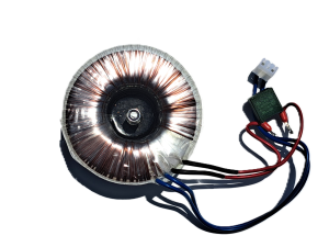
Electrical
- Low-voltage sensor system (5V–24V logic)
- Pulse output (digital signal)
Signal type
- Square wave pulse train
- Frequency = motor speed (RPM)
Mechanical interface
- Mounted on:
- Motor shaft OR gearbox housing
- Coupled via:
- Magnet ring / encoder wheel
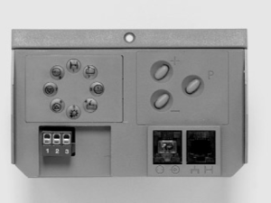
How limits are actually set
The system does NOT use physical limit screws like older motors.
Instead:
Programming process:
- Motor runs to fully open position
- Controller records RPM pulse count
- Motor runs to fully closed position
- Controller stores second reference point
- System calculates full travel range
This is why it is called:
“electronic limit setting system”
Failure symptoms (very important in real use)
If the RPM limit assembly fails:
Typical symptoms
- Door runs but does NOT stop correctly
- Door overshoots open/close position
- Stops mid-travel randomly
- “No limit set” or similar fault behavior
- Motor runs continuously without reference
Root causes
- Faulty RPM sensor
- Broken encoder magnet ring
- Loose wiring to control PCB
- Controller not receiving pulses
Testing method (field check)
Quick diagnostic:
- Check motor rotation manually (service mode)
- Measure sensor output:
- Should show pulsing voltage on multimeter/oscilloscope
- If motor turns but no pulses:
RPM assembly is faulty
(The Company reserves the right to amend product specifications and information without notice.)